Print2CAD 2022 - Reference Manual
Enhanced Vectorization Settings
This menu is used when you want to refine the vectorization of raster images. A firm understanding of vectorization methods is necessary here. To set the optimum settings for different scan types, please click one of the buttons in the middle of the interface.
Parameter: Maximum Line Weight in Pixel
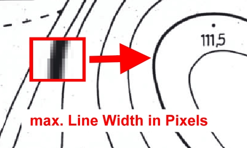
The maximum line weight is an important parameter for a line and hatch recognition and for closing a gap jump. With the help of this parameter the vectorization can separate pixel traces from the pixel areas and use different vectorization methods. A parameter uses the thickest line width in your raster picture (simply zoom in to detail and count pixels on the screen).
Parameter: Minimum Pixel Groups Length
With the help of this parameter you can clean up the free pixels or fill the holes in pixel traces.
All pixel groups with a length less than or equal to the specified number “B” get purged.
If you activate the function, “Fill Holes in Pixel Traces” under “Vectorization 1” or “Vectorization 2”, this same parameter will be used also for max. hole size in the pixel trace.
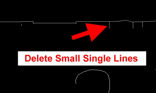
Parameter: Smallest Single Line after Raster to Vector
This parameter allows to delete small separate lines after raster to vector method “center line tracing”. This parameter will be used only for long pixel traces.
Small and middle pixel traces will not be cleaned with the help of this parameter.
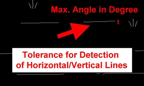
Parameter: Angle Tolerance for Horizontal, Vertical and 45 Degree Line Detection
This function allows to define max. angle change between the beginning and the end of a polyline after “Center Line Tracing” for the detection of Horizontal, Vertical and 45 Degree lines. If the start and end angle is in the tolerance, the program will check that all vertexes are on a single line using the smoothing tolerance.
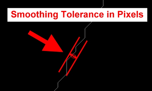
Parameter: Smoothing Tolerance in Pixels
This parameter is the tolerance in pixels for the smoothing iterations.
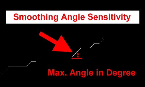
Parameter: Smoothing Angle Sensitivity
This parameter should be more than 45 degrees and less than 90 degrees. If the angle between two vertexes is bigger than this parameter the smoothing will not done.
This is important for keeping the edges in polylines after “Center Line Tracing.”
Parameter: Iteration Number for Smoothing
The number of smoothing iterations can be adjusted. The more iterations, the smoother the polylines will be. On the other hand, it is possible that important corners in the drawings will disappear.
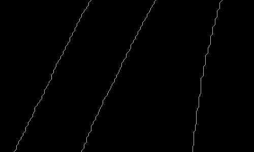
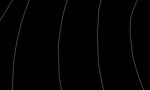
“Center Line Tracing” Polylines before Smoothing Iterations
“Center Line Tracing” Polylines after Smoothing Iterations
BacktoCAD Technologies, LLC
601 Cleveland St, Suite 380
Clearwater, FL 33755, USA
Email: bc-sales@cad-pdf.com
Phone: (727) 303 0383
© Copyright 2020 BackToCAD Technologies, LLC. All rights reserved. Kazmierczak® is a registered trademark of Kazmierczak Software GmbH. Print2CAD, AzubiCAD, and CAD2Print are Trademarks of BackToCAD Technologies LLC. CADconv is a Trademark of Expert Robotics Inc.. DWG is the name of Autodesk’s proprietary file format and technology used in AutoCAD® software and related products. Autodesk, the Autodesk logo, AutoCAD, DWG are registered trademarks or trademarks of Autodesk, Inc., and/or its subsidiaries and/or affiliates in the USA and/or other countries. All other brand names, product names, or trademarks belong to their respective holders. This website is independent of Autodesk, Inc., and is not authorized by, endorsed by, sponsored by, affiliated with, or otherwise approved by Autodesk, Inc. The material and software have been placed on this Internet site under the authority of the copyright owner for the sole purpose of viewing of the materials by users of this site. Users, press or journalists are not authorized to reproduce any of the materials in any form or by any means, electronic or mechanical, including data storage and retrieval systems, recording, printing or photocopying.
