Print2CAD 2022 - Reference Manual
Solidization of Raster Pictures
In this setting all pixel images are vectorized and embedded into the drawing as an entity Solid (filled rectangle). All solids that have close to the same color will be connected to create one common solid. This option is ideal for colorful pictures or bad quality scans.
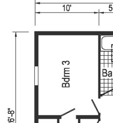
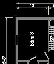
Original Raster Image in PDF
Image Solidization in DWG
Parameter: Fill Small Holes in Pixel Traces
This setting fills the small holes in the pixel traces.

Parameter: Fill all Holes in Pixel Traces
This setting allows all holes in the pixel traces to be filled.

Parameter: Close Open Pixel Traces
Often older scanned drawings will contain open pixel traces. This setting will prompt the program to close these open spaces. Under “For Experts Only” the user can select the distance between pixels.
Parameter: Cleanup of Free Pixels
Often older scanned drawings will have free pixels. Selecting this feature will ensure the removal of these unwanted pixels for a cleaner converted file.
Parameter: Thicken Pixel Traces
This setting will add a layer of pixels to the outer edge of the pixel trace.

Parameter: Thin the Pixel Traces
This setting removes one layer of pixels from the outer edge of the pixel trace.

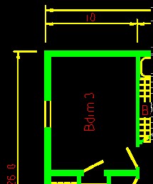
Parameter: Assign Chromatic Colors to Layers
This setting assigns a separate color to entities from different layers. This way the user can better see the layer separation on the screen.

Original Raster Image in PDF
Color Entities Solid in DWG
Parameter: Enhanced Recognition of Hatch Boundaries
This program tries to find separate vector and hatch areas from in common pixel traces.
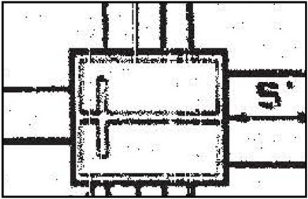
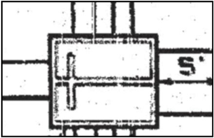
Parameter: Repair Raster Pictures Using Blurring
A good method to repair bad quality scanned images is to blur these images and then convert them into black/white images using the threshold. By blurring, the free pixels are removed, and the holes in the pixel traces are closed.
Original
Picture after Blurring and Thresholding
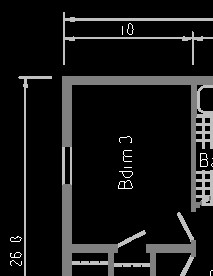
Parameter: Vectorize Small Elements as Lines
The program vectorizes all small pixel traces in lines using the “center line tracing” method.

Original Raster Image in PDF
Small Elements as Lines
Convert Digital Photos as Hatch Entities “Solid”
The program vectorizes digital photos as color fillings in the form of an element Solid. Solids are very fast rectangle hatches used in CAD systems.
Output Images in Original Resolution
When selecting this option, all raster images are handled in their original resolution. For large raster images enabling this option may cause the resulting DWG / DXF file to contain millions of solid hatches.
Limited Dimension of Raster Pictures
When selecting this option, all pixel images are first scaled so that none of the dimensions are over the maximum values specified. The proportions of the image are not changed.
Handle Raster Images in Black and White
When selecting this option, the vectorized image is first converted into a black / white image and then vectorized. The threshold value for the color black is used.
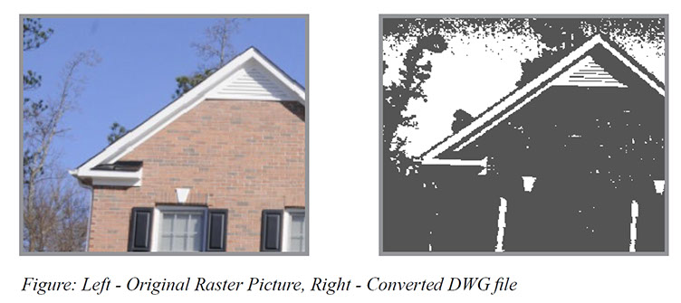
Original Raster Image in PDF
Converted DWG Output
(with black background)
Handle Raster Images in RGB or Index Colors
When selecting this option, the contrasts in color will be increased and then the image will be vectorized. The threshold value for the color black and white is considered.
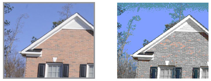
Original Raster Image in PDF
Converted DWG Output
(with black background)
Ignore White Color
If this option is selected, all pixels which are brighter than the threshold of the color white in color images, and brighter than the threshold of the color black in b/w images, won‘t be converted. This creates coherent hatching without any white spaces in between.
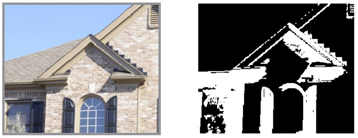
Original Raster Image in PDF
Converted DWG Output
(with black background)
Contour Finding and Cartoonization of Digital Photos
This program functions helps to find the contours in digital photos. Contours can be explained simply as a curved joining of all the continuous points (along the boundary), that have the same color or intensity. The contours are a useful tool for vectorization of digital photos.
Contour Finding Methods
This program offers five different contour finding methods.
Method 1: Canny Method
This method was invented by John F. Canny a professor of computer science at the University of California, Berkeley. Canny‘s method is based on a gradient operator. The key idea here is to use two different thresholds to determine which point should belong to a contour.
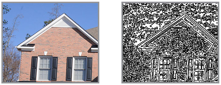
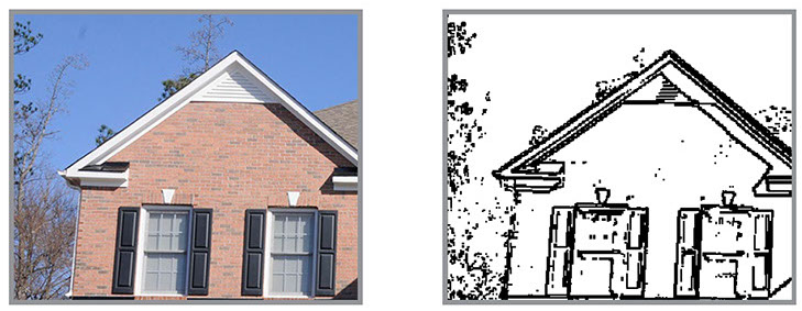
Method 2: Sobel Method
Original Raster Image in PDF
Converted DWG Output
(with white background)
In Irwin Sobel‘s method we apply directional filters to detect edges in raster images to create contours for the vector image.
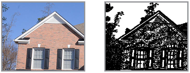
Method 3: Shaar Method
Original Raster Image in PDF
Converted DWG Output
(with white background)
The method of Hanno Scharr is a modification of Sobel‘s method for edge detecting in raster images. This method is preferred when more accurate estimates of the gradient orientation is required.
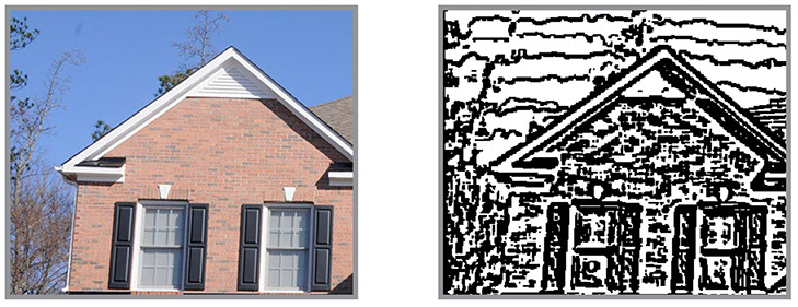
Method 4: Laplace Method
Original Raster Image in PDF
Converted DWG Output
(with white background)
The Laplace method is named after its founder Pierre-Simon De Laplace. The Laplace method uses the simplest elliptic operator to detect contours.
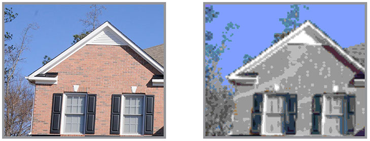
Method 5: Cartoonization
Original Raster Image in PDF
Converted DWG Output
(with white background)
The method of cartoonization creates solid hatches out of digital images, which is reminiscent of the appearance of cartoons. These hatched areas are made from the DWG element Solid.
Original Raster Image in PDF
Converted DWG Output
(with white background)
BacktoCAD Technologies, LLC
601 Cleveland St, Suite 380
Clearwater, FL 33755, USA
Email: bc-sales@cad-pdf.com
Phone: (727) 303 0383
© Copyright 2020 BackToCAD Technologies, LLC. All rights reserved. Kazmierczak® is a registered trademark of Kazmierczak Software GmbH. Print2CAD, AzubiCAD, and CAD2Print are Trademarks of BackToCAD Technologies LLC. CADconv is a Trademark of Expert Robotics Inc.. DWG is the name of Autodesk’s proprietary file format and technology used in AutoCAD® software and related products. Autodesk, the Autodesk logo, AutoCAD, DWG are registered trademarks or trademarks of Autodesk, Inc., and/or its subsidiaries and/or affiliates in the USA and/or other countries. All other brand names, product names, or trademarks belong to their respective holders. This website is independent of Autodesk, Inc., and is not authorized by, endorsed by, sponsored by, affiliated with, or otherwise approved by Autodesk, Inc. The material and software have been placed on this Internet site under the authority of the copyright owner for the sole purpose of viewing of the materials by users of this site. Users, press or journalists are not authorized to reproduce any of the materials in any form or by any means, electronic or mechanical, including data storage and retrieval systems, recording, printing or photocopying.
