
Optimierung 1:
Seitenauswahl, Linientyperkennung, Koordinatenskalierung
Seitenauswahl, Linientyperkennung, Koordinatenskalierung
Auswahl von PDF-Seiten
- Der Benutzer kann bei mehrseitigen PDF-Dateien auswählen, welche Seiten konvertiert werden sollen, oder einfach alle Seiten in einer Ausführung konvertieren. Die ausgewählten Seiten sollten durch ein Semikolon getrennt werden. (zB 1; 4; 12; 34). Um mehrere Seiten hintereinander (von - bis) umzuwandeln, können Sie einen Bindestrich verwenden (z. B. 12-18).
Automatische Erkennung von Linientypen und Linienmustern
- Die Möglichkeit, eine Linie mit Linientypen in PDF-Dateien zu definieren, existiert, wird aber selten genutzt, da die Gefahr besteht, dass die Linientypen im PDF ungenau erscheinen. Fast alle PDF-Schnittstellen in CAD-Systemen erstellen eine statische Kopie der Linie mit kleinen einzelnen Bindestrichen.
- Mit Hilfe spezieller Funktionen der künstlichen Intelligenz kann Print2CAD die meisten fragmentierten Linien erkennen. Die kleinen Striche können mit dem Linientyp „gestrichelt“ an die gemeinsame Linie gebunden werden.
- Auch bei der automatischen Erkennung kann es noch zu Fehlern kommen. Um die Anzahl der Fehler zu minimieren, kann der Benutzer die Linientypbereiche auch mit dem internen Tool unter Artificial Intelligence „Enhanced Line Type Recognition“ markieren.
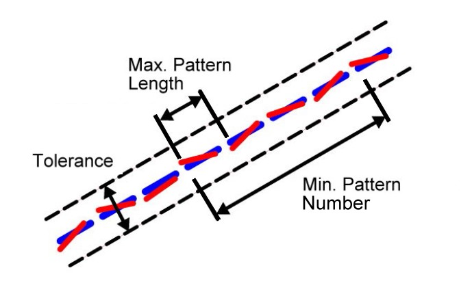
Parameter: Minimale und maximale Musterlänge
- Die Musterlänge ist die wichtigste Information für eine korrekte Linientyperkennung. Das Muster ist definiert als die Länge in der Print2CAD-Einheit (siehe „Konfiguration“) einer sich wiederholenden Folge von Strichen und Leerzeichen dazwischen.
.jpg)
Parameter: Toleranz
- In Bezug auf die Enden kleiner Striche versucht das Programm, sich an eine gemeinsame Linie zu binden, die normalerweise nicht auf einer geraden Linie liegt. Die Toleranz gibt Auskunft über den maximalen Abstand vom Beginn des Endes eines Strichs bis zur hypothetischen Geraden.
Parameter: Linientyp
- Das Programm Print2CAD kann den Linientyp „Gestrichelt“, „Gestrichelter Punkt“ und „Gepunktet“ erkennen.
Parameter: Linientyp Neigung
- Das Programm Print2CAD kann Linien mit Linientyp unter definierten Winkeln erkennen.
Skalierung von Koordinaten
- Koordinaten in PDF-Dateien haben normalerweise eine Auflösung von 300 DPI, was bedeutet, dass ein Zoll (25,4 mm) 300 Pixel und Koordinatenpunkte entspricht.
- Der Maßstab einer PDF-Zeichnung kann leider nur aus der Kopfzeile eines Bauplans abgerufen werden.
- In einer korrekten PDF-Datei ist der Maßstab der Zeichnung auch der Skalierungsfaktor der Koordinaten. Beispiel: Beim Maßstab 1:50 beträgt der Skalierungsfaktor 50.
- Wenn der Skalierungsfaktor die Koordinaten nicht gut korrigiert, benötigen Sie die korrekte Kalibrierung mit Hilfe der Schnittstelle „Enhanced Calibration of Coordinates“.
Helle Elemente auf hellem Hintergrund löschen
- PDF-Dateien enthalten oft unsichtbare weiße Elemente auf einem weißen Hintergrund. Es ist möglich, diese Elemente während der Konvertierung zu löschen, um die Dateigröße und die Konvertierungszeit zu verringern. Die Grenzgröße der Farbhelligkeit (von 1 bis 255) kann bestimmt werden.
Abschneiden von Schraffuren und anderen Elementen auf einem PDF-Abschneiderahmen
- PDF-Dateien enthalten oft Schnittränder für Linien und andere PDF-Objekte. Die Standardeinstellung für das Abschneiden von Rändern ist auf „Aus“ gesetzt. Das Weglassen dieser Clipping-Grenze ist eine sehr gute Methode, um viele zusätzliche Informationen außerhalb einer Clipping-Grenze zu konvertieren.
© Copyright 2023 Back2CAD AI Technologies LLC. All rights reserved. Kazmierczak® is a registered trademark of Kazmierczak Software GmbH. Print2CAD, CADdirect, CAD.direct, CAD Direct, CAD.bot, CAD Bot, are Trademarks of Back2CAD AI Technologies LLC. DWG is the name of Autodesk’s proprietary file format and technology used in AutoCAD® software and related products. Autodesk, the Autodesk logo, AutoCAD, DWG are registered trademarks or trademarks of Autodesk, Inc. All other brand names, product names, or trademarks belong to their respective holders. This website is independent of Autodesk, Inc., and is not authorized by, endorsed by, sponsored by, affiliated with, or otherwise approved by Autodesk, Inc. The material and software have been placed on this Internet site under the authority of the copyright owner for the sole purpose of viewing of the materials by users of this site. Users, press or journalists are not authorized to reproduce any of the materials in any form or by any means, electronic or mechanical, including data storage and retrieval systems, recording, printing or photocopying.